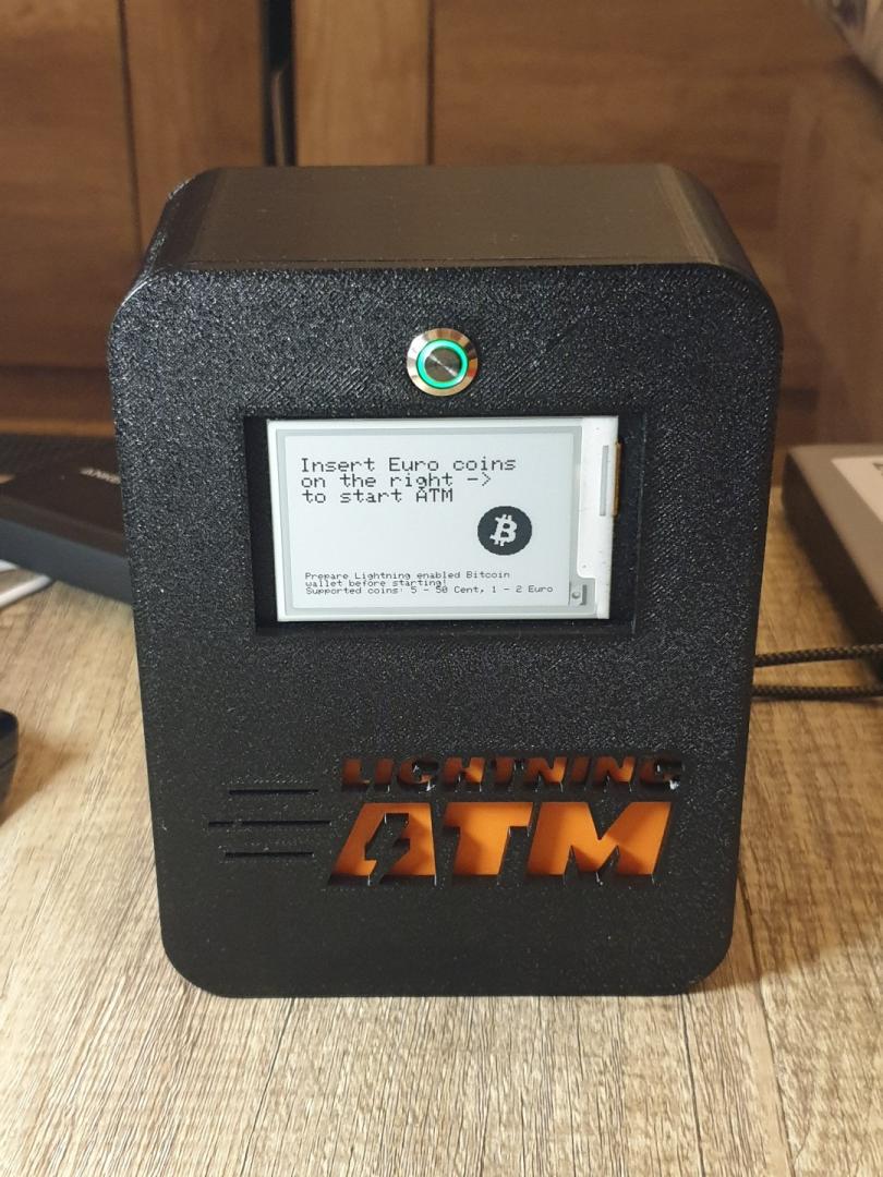
Hardware Assembly
This section covers wiring the electronics together. Gather the parts from the Bill of Materials first. If you also want to print an enclosure, see 3D Printed Case.
Assembly order
Set the step-up converter’s output voltage before connecting the coin acceptor (it runs on 12 V). See Programming the Coin Acceptor.
Wire the e-paper display to the ESP32 — see the pin tables in Wiring & Pinout.
Connect the coin acceptor and its blocking MOSFET (Wiring & Pinout).
Connect the LED push button (Wiring & Pinout).
Cross-check everything against the circuit diagram for your board below.
Note
Building with the JC3248W535C touchscreen board? Steps 2 and 4 don’t apply — display and button are integrated. Only the coin acceptor and MOSFET are wired (three wires total, see Wiring & Pinout).
Circuit diagrams
There are two wiring options depending on which ESP32 / display-driver combination you use. (The JC3248W535C touchscreen build has no diagram — its handful of wires is fully described in Wiring & Pinout.)
1. Standard ESP32 with a separate display / driver board
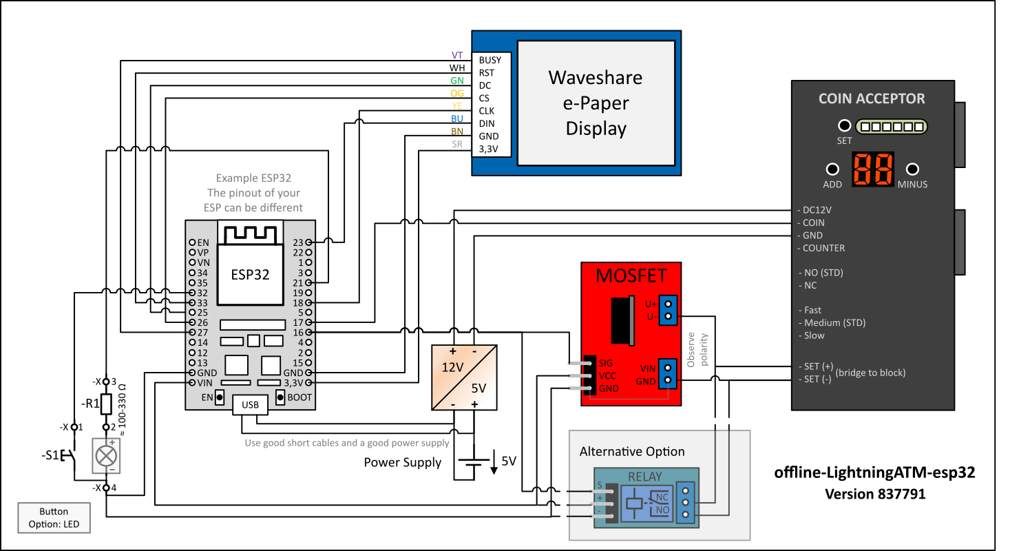
Wiring for a standard ESP32 (the “Generic” board profile).
2. Waveshare ESP32 with an integrated driver board and a separate display
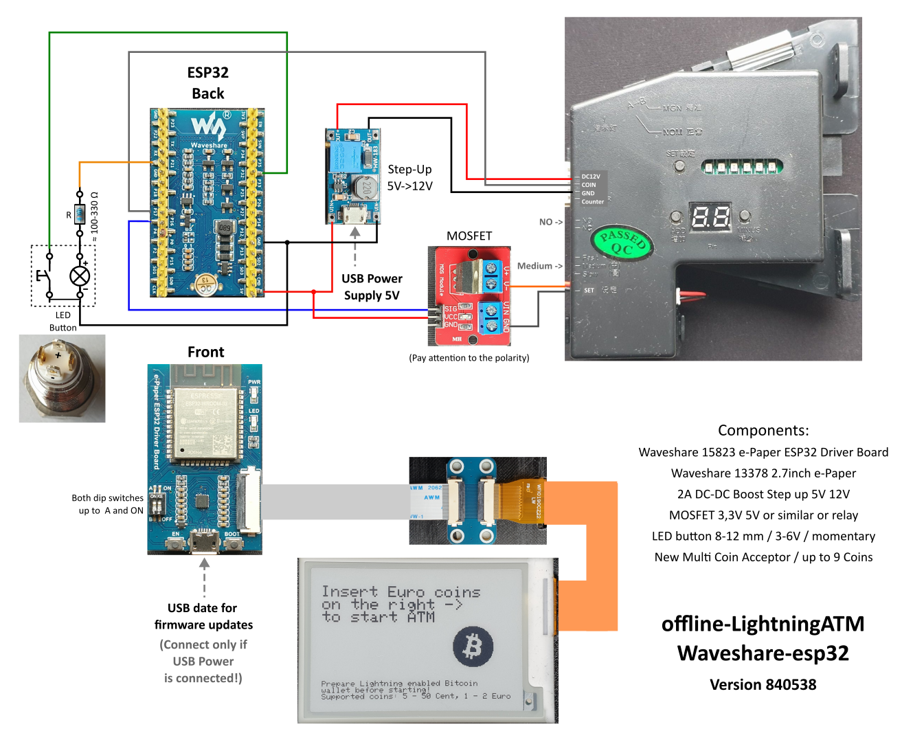
Wiring for the Waveshare ESP32 driver board (the “Waveshare” board profile).
Note
Higher-resolution and editable sources are in the repository: standard ESP32 (SVG), Waveshare ESP32 (SVG), and the editable Visio source (.vsdx).


Construction photos
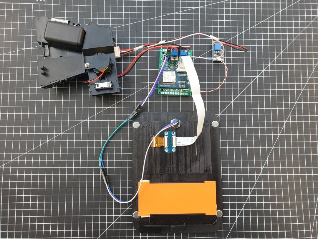
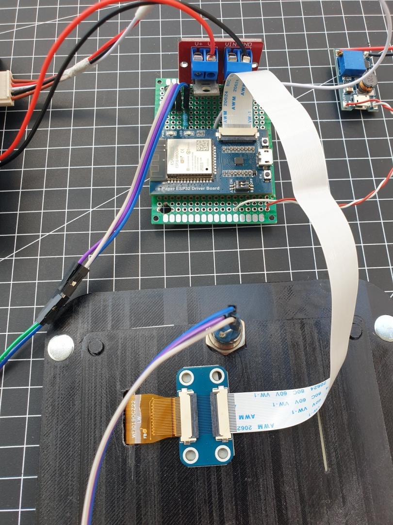
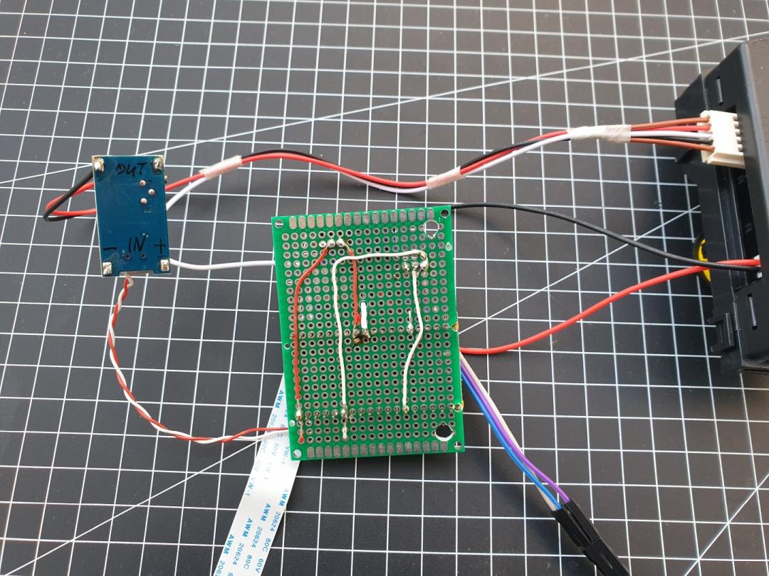
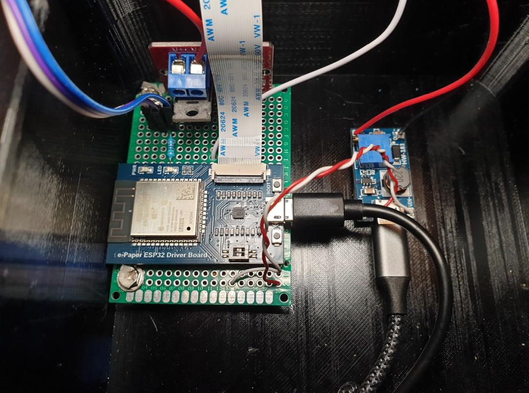
The following photos show a build using the Waveshare ESP32 driver board.